
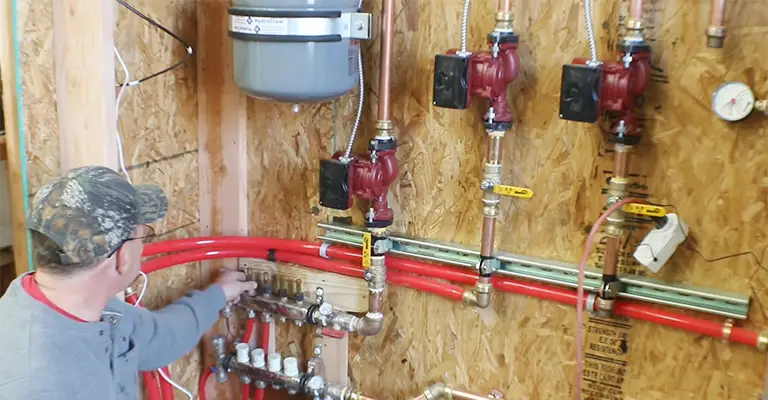
Radiant heating systems provide comfortable and efficient heating for homes and buildings by circulating hot water through tubing installed in floors, walls, or ceilings.
A circulator pump is a critical component of a radiant heating system, as it is responsible for moving the hot water through the piping network.
Properly sizing the circulator pump is essential for ensuring the system can deliver the required heat load and operate efficiently.
Sizing a circulator pump for a radiant heating system involves several factors, including the size of the system, the heat load requirements, the temperature differential, and the pressure drop in the piping system.
Here are the general steps to follow:
1. Determine The Heat Load Requirements
The heat load is the amount of heat energy required to maintain the desired temperature in the space.
This can be calculated based on the size of the room, insulation level, climate, and other factors. The heat load is typically measured in BTUs (British Thermal Units) per hour.
2. Determine The Flow Rate
The flow rate is the amount of water that needs to circulate through the system to deliver the required heat load.
This can be calculated based on the heat load and the temperature differential between the supply and return lines of the system.
3. Calculate The Pressure Drop

The pressure drop is the amount of pressure that is lost as water flows through the piping system. This can be calculated based on the flow rate, the pipes’ length and diameter, and the system’s fittings and valves.
4. Select A Pump
Once you have determined the required flow rate and pressure drop, you can select a circulator pump that can deliver the required performance. Pumps are typically rated in terms of flow rate and head pressure.
5. Verify The Pump Selection
Verifying that the selected pump can deliver the required flow rate and pressure drop for your specific system is essential.
You may need to consult the manufacturer’s specifications or perform additional calculations to ensure that the pump is appropriate.
Steps For Sizing A Circulator Pump For Radiant Heat
Before deciding on a Circulator Pump, some important features should be considered.
Materials of construction (cast iron, bronze, stainless steel), flow rate (GPM, or Gallons per Minute), head loss (in feet of head), horsepower (HP), power supply (V), and connection types/sizes (flanged, threaded, sweat) are among the features.
The cast iron flanged type is the most common type of circulator pump for closed-loop radiant or hydronic heating.
It is typical to find stainless steel or bronze circulators used for open-loop hydronic/radiant heating and domestic hot water recirculation applications.
Connecting the circulator to existing water lines using threaded and sweat connection types in the later application types is often easier.
Taco circulators and Grundfos circulators operate on 115 volts, 60 Hz, by default. It is usually custom ordered for other models, such as with the 230V power supply or with the outlet plug.
An appropriate circulator pump size is based on the heat load and head loss (pressure drop) in a given zone.
Step 1
By knowing the heat load (in BTUs) for a given zone, you can calculate the flow rate of your circulator pump. For hydronic or radiant applications, it can be applied as follows:
GPM = 0.002*BTU/(Temperature Drop, F)
There is a temperature drop between the supply and return temperatures of the circulator, and a GPM flow rate is the amount of flow generated by the circulator.
As most radiant heating systems use a 20F temperature drop, the formula can be adapted as follows:
1 GPM = 10,000 BTU/hr,
In other words, the circulator must supply a flow of 1 gallon per minute for every 10,000 BTUs of heat load.
In this case, a circulator pump should flow at least 10 Gallons per Minute at a pressure drop of 100,000 BTU/hr.
The above equation does not apply to snow melt systems with a 50/50 mix of glycol and water:
1 GPM = 11,000 BTU/hr
Step 2
Next, calculating the head loss or pressure drop within the system is necessary.
Hydraulic or radiant heating systems suffer from head loss resulting from friction between the water and the pipes/tubing, which limits flow rates.
Even though radiant heat manifolds and PEX tubing sizing are two separate topics, let’s assume, for example, that a radiant heat manifold has eight outlets with 1/2″ PEX tubing installed at 300 ft per loop and the system requires 72,000 BTUs.
Using the formula above, we can determine the flow rate required for our given zone: 72,000/10,000 = 7.2 GPM.
In a manifold, the flow rate over every circuit is equal to the flow rate divided by the number of circuits:
Each circuit is estimated to use 0.9 GPM (assuming that all circuits are equally balanced).
Calculating a pressure drop per foot of PEX tubing in accordance with a Pressure Drop Table or Pressure Drop Chart is possible with a PEX tubing manufacturer’s chart.
NOTE: Manufacturers may provide pressure drop data in pounds per square inch (PSI) and feet per head (FT).
For conversion, use the following equation: 1 psi = 2.3 ft of the head (for freshwater), and 1 ft of head = 0.43 psi.
Based on this example, the pressure drop due to 1 ft of 1/2″ PEX tubing would be approximately 0.03 ft of head).
Considering that each individual PEX tubing circuit is 300 ft long, the pressure drop per circuit would be 0.03 x 300 = 9.0 ft of head.
The pressure drop per circuit in PEX tubing is the same as that of the entire zone since PEX tubing circuits run parallel to each other. Hence, the total pressure drop is 9.0 feet.
Now that we have the entire specifications for the circulator pump, we have 7.2 GPM flow at 9.0 feet of head pressure.
There are also other components installed within a zone that has to be considered when sizing a circulator pump (such as the radiant heat manifold itself, fittings, check valves, mixing valves, balancing valves, heat exchangers, PEX tubing lengths, etc.).
A manufacturer will provide pressure drop information in the form of a technical specification or submittal sheet.
NOTE: A pump head refers to the force generated by the circulator due to overcoming pressure drop (due to pipes, fittings, and valves).
When the pump head is part of a closed system, the building height does not determine the pump head. There is no calculation based on height (#10 on the Scheme above).
If real conditions are present, we might add an extra 2 feet of the head, making the pressure drop 11 ft.
Step 3:
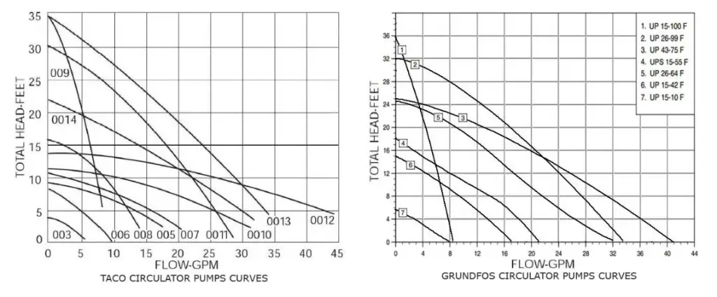
A Circulator Pump Curve Chart must be used to match the data with an appropriate pump.
For example, we can consider Taco 008, Taco 009, and Taco 0010 circulators that fit our needs.
Despite this, Taco 009 circulator is designed for use only in high-head and low-flow applications, so if the flow requirements were to increase slightly, the circulator’s performance would suffer.
Similar conditions apply to the Taco 0010 model. A pump designed for high flow and low head applications will significantly degrade its performance if the pressure drop in the system is changed by adding or modifying something to the system.
The Taco 008 circulator would be the most appropriate for the system based on the conditions described.
Final Words
During system analysis, you can determine the size and type of circulator that will work best for your system. This information was collected from https://www.pexuniverse.com.